Sample and Hold Board: Difference between revisions
(New page: 400px||Sample and Hold Board) |
|||
| (13 intermediate revisions by the same user not shown) | |||
| Line 1: | Line 1: | ||
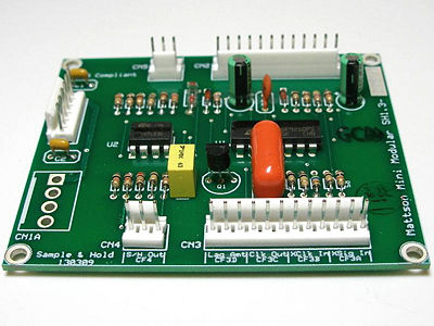
[[Image:Sample-and-Hold-Board.jpg|400px||Sample and Hold Board]] | [[Image:Sample-and-Hold-Board.jpg|400px||Sample and Hold Board]] | ||
[http://www.youtube.com/watch?v=9aszeOovm6o| Sample and Hold Basic Operations Video] | |||
The Sample and Hold samples a source waveform at a set clock rate and outputs the voltage that was present at the sample point. It holds that voltage level until the clock cycles. | |||
The Sample and Hold contains an internal triangle Low Frequency Oscillator and an internal clock (a square wave LFO). Either one can be substituted by applying an external signal to the appropriate external input jack. | |||
The input jacks must be interrupting-type for the S/H to operate properly. | |||
The clock output buffers and outputs either the internal or any external clock to the clock output. This allows for timing synchronization with other modules. | |||
The LED's indicate the oscillator and clock rates being utilized, internal or external | |||
The track and hold function allows the internal or external oscillator source to pass though to the output during 1/2 of the clock cycle. When the clock switches states from low to high, it samples the input source and holds the voltage sampled until the clock switches states and goes low again. | |||
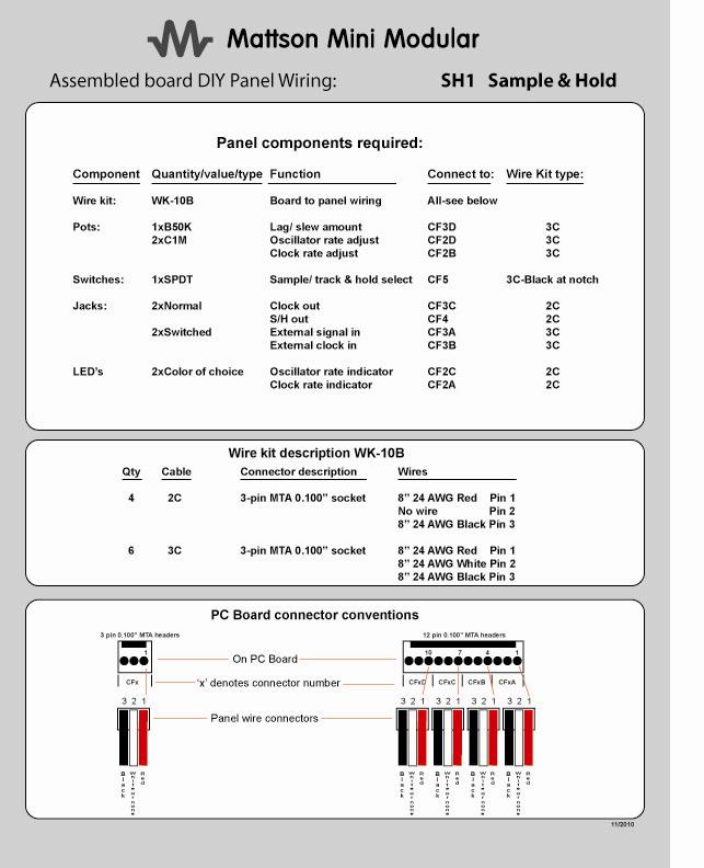
== Wiring information: == | |||
[[Image:SH1_module_panel_wiring.jpg]] | |||
[[media:SH1_module_panel_wiring.pdf|Click for Adobe PDF version.]] | |||
== Availability == | |||
This module is available | |||
'''$89.00''' | |||
To order, visit the [http://www.mattsonminimodular.com/shop MMM Store] | |||
[[DIY single module PC board dimensions and mounting suggestions |Go to board dimensions and mounting]] | |||
[[DIY Panel wiring general conventions |Go to general wiring conventions information]] | |||
[[DIYcisions DIYcisions |Back to DIY main menu]] | |||
Latest revision as of 16:37, 7 June 2014
Sample and Hold Basic Operations Video
The Sample and Hold samples a source waveform at a set clock rate and outputs the voltage that was present at the sample point. It holds that voltage level until the clock cycles.
The Sample and Hold contains an internal triangle Low Frequency Oscillator and an internal clock (a square wave LFO). Either one can be substituted by applying an external signal to the appropriate external input jack.
The input jacks must be interrupting-type for the S/H to operate properly.
The clock output buffers and outputs either the internal or any external clock to the clock output. This allows for timing synchronization with other modules.
The LED's indicate the oscillator and clock rates being utilized, internal or external
The track and hold function allows the internal or external oscillator source to pass though to the output during 1/2 of the clock cycle. When the clock switches states from low to high, it samples the input source and holds the voltage sampled until the clock switches states and goes low again.
Wiring information:
Availability
This module is available
$89.00
To order, visit the MMM Store
Go to board dimensions and mounting

