Sample and Hold: Difference between revisions
No edit summary |
|||
| (26 intermediate revisions by 4 users not shown) | |||
| Line 1: | Line 1: | ||
[[Image:Sample-Hold-3.jpg|400px||Sample & Hold]] | |||
[http://www.youtube.com/watch?v=9aszeOovm6o| Sample and Hold Basic Operations Video] | |||
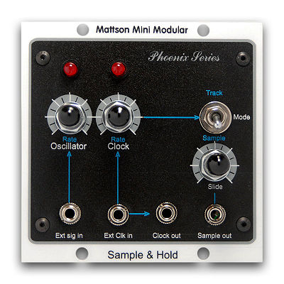
Internal Triangle LFO for sample source. Can be replaced by inputting | Internal Triangle LFO for sample source. Can be replaced by inputting | ||
an external source into the Ext. Osc. In jack. | an external source into the Ext. Osc. In jack. | ||
| Line 5: | Line 9: | ||
inputting an external trigger source into the Ext. Clk. In jack. Source | inputting an external trigger source into the Ext. Clk. In jack. Source | ||
is sampled on the negative to positive transition of the clock. | is sampled on the negative to positive transition of the clock. | ||
[[Image:MMM_Sample_and_Hold.JPG]] | |||
'''Pseudo Random output''' | |||
Track & Hold / Sample & Hold select switch. Bypasses the internal sample | Track & Hold / Sample & Hold select switch. Bypasses the internal sample | ||
| Line 11: | Line 21: | ||
high level, the source voltage present at the time of positive clock | high level, the source voltage present at the time of positive clock | ||
transition is "held" at the output until the clock transitions low again. | transition is "held" at the output until the clock transitions low again. | ||
[[Image:MMM_Track_and_Hold.JPG]] | |||
'''Track and Hold output''' | |||
Slide allows for a slew or glide to be added between output transition voltages. | Slide allows for a slew or glide to be added between output transition voltages. | ||
[[Image: | [[Image:MMM_Sample_and_Hold_w_lag.JPG]] | ||
'''Slide adds transition glide to output''' | |||
Clock out allows for the sample clock to be used as a timing sync source to other modules. If an external clock source is present at the Ext Clk in jack, the external clock signal is buffered and present at this jack. | |||
== Availability == | |||
This module is currently available. | |||
'''$195.00''' | |||
[[Sample and Hold Board |Assembled/ tested board only:]] | |||
'''$89.00''' | |||
== Info == | |||
'''Current draw:''' | |||
V+= 12.5mA | |||
V-= 11.70mA | |||
'''PCB board dimensions:''' | |||
3.125" (3-1/8") 79.38mm X 2.625" (2-5/8") 66.68mm | |||
Mounting holes: 0.125" (1/8") 3.18mm (for 4-40 screw) 4 holes, one in each corner | |||
Mounting hole spacing; Length: C-C= 2.925" 74.3mm, Width: C-C= 2.425" 61.6mm | |||
Latest revision as of 16:36, 7 June 2014
Sample and Hold Basic Operations Video
Internal Triangle LFO for sample source. Can be replaced by inputting an external source into the Ext. Osc. In jack.
Internal square wave LFO for sample rate selection. Can be replaced by inputting an external trigger source into the Ext. Clk. In jack. Source is sampled on the negative to positive transition of the clock.
Pseudo Random output
Track & Hold / Sample & Hold select switch. Bypasses the internal sample strobe in Track position and allows the source to go directly to the output during the lower clock level. When the clock transitions to a high level, the source voltage present at the time of positive clock transition is "held" at the output until the clock transitions low again.
Track and Hold output
Slide allows for a slew or glide to be added between output transition voltages.
Slide adds transition glide to output
Clock out allows for the sample clock to be used as a timing sync source to other modules. If an external clock source is present at the Ext Clk in jack, the external clock signal is buffered and present at this jack.
Availability
This module is currently available. $195.00
Assembled/ tested board only: $89.00
Info
Current draw:
V+= 12.5mA
V-= 11.70mA
PCB board dimensions:
3.125" (3-1/8") 79.38mm X 2.625" (2-5/8") 66.68mm
Mounting holes: 0.125" (1/8") 3.18mm (for 4-40 screw) 4 holes, one in each corner
Mounting hole spacing; Length: C-C= 2.925" 74.3mm, Width: C-C= 2.425" 61.6mm


