4x Gate Delay: Difference between revisions
| Line 15: | Line 15: | ||
'''Gate on LED:''' | '''Gate on LED:''' | ||
Indicates that a gate is present or a CV input has reached the level to initiate the delay sequence. | Indicates that a gate is present or a CV input has reached the level to initiate the output delay sequence. | ||
'''Delay:''' | '''Delay:''' | ||
| Line 21: | Line 21: | ||
'''Red LED:''' | '''Red LED:''' | ||
Indicates that the delay time has been reached and the delayed gate is active on that channel. | Indicates that the delay time has been reached and the delayed gate output is active on that channel. | ||
'''Out (1-4):''' | '''Out (1-4):''' | ||
Revision as of 09:35, 11 May 2009
Features
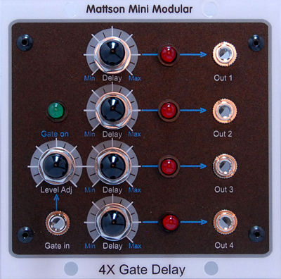
The 4X Gate Delay serves as a gate generating module. If minimum delay is selected, it can be used as a four-gate multiple.
The gate delay responds to an external gate and generates four gates. Each gate output can be delayed independently.
The "gate in" is sort of mis-labeled. A CV can be utilized, such as a 1V/O keyboard voltage, the Level Adj can be used to determine at what point the gate delay process will begin. You can set it to not generate any gates until a specific key or above has been played. As soon as a key lower than the set level is played, all gates drop. If the input drops before the set delay time is reached, the gate for that channel won't be generated and the delay sequence is reset for the next delay process.
Gate in: Input for an external gate or CV
Level Adj: Sets the level that a CV input will start the delay sequence.On the Mattson Modular, If a gate is used as an input, the gate voltage is higher (+15V) than any preset level and will work automatically without having to re-adjust the level. It also allows for lower level gates (+5V, +10V) from other systems to be converted to a +15V gate.
Gate on LED: Indicates that a gate is present or a CV input has reached the level to initiate the output delay sequence.
Delay: Sets the amount of time that gate output will delay after the delay sequence is initiated.
Red LED: Indicates that the delay time has been reached and the delayed gate output is active on that channel.
Out (1-4): The channel delayed gate outputs.
Availability
This module is currently available.
