QuAD /ASR Envelope Generator Board: Difference between revisions
No edit summary |
No edit summary |
||
| Line 21: | Line 21: | ||
'''ASR mode:''' (Attack-Sustain-Release) When a gate is present at the channel input, The Attack stage is initiated, self completes and the output sustains at full output until the gate is dropped. When the gate is dropped, The Decay stage is initiated and the output drops to 0 at the decay rate. | '''ASR mode:''' (Attack-Sustain-Release) When a gate is present at the channel input, The Attack stage is initiated, self completes and the output sustains at full output until the gate is dropped. When the gate is dropped, The Decay stage is initiated and the output drops to 0 at the decay rate. | ||
'''Gate Input:''' The Gate inputs are for a 5-15V gate input to initiate the envelope sequence. The gate inputs are cascaded. A gate input applied to channel 1 will initiate the Attack stage of all four envelope generators. A gate input patched into a different channel will interrup the cascade and apply the new gate voltage on the selected and all subsequent channels. | '''Gate Input:''' The Gate inputs are for a 5-15V gate input to initiate the envelope sequence. The gate inputs are cascaded. A gate input applied to channel 1 will initiate the Attack stage of all four envelope generators. A gate input patched into a different channel will interrup the cascade and apply the new gate voltage on the selected and all subsequent channels. | ||
Revision as of 19:10, 9 August 2010
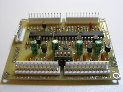
The QuAD /ASR Envelope Generator consists of 4 identical channels. This is designed as a utility module for basic Envelope utilization.
Each channel has an Attack and Decay user control.
There is a 4x dip switch on board for user selection of independent channel EG function. The switch numbers 1-4 correspond to the channel number selection. Up (away from the channel number) selects ASR mode and down (closest to the channel number) selects AD mode.
If the DIY'er prefers to remote this function to front panel switches, the DIP switch is socketed and can be removed. The DIP pins can be run to panel switches as follows: (open=AD mode, closed=ASR mode)
Channel 1: Pins 1 and 8
Channel 2: Pins 2 and 7
Channel 3: Pins 3 and 6
Channel 4: Pins 4 and 5
AD Mode: (Attack-Decay) When a gate is present at the channel input, the Attack stage is initiated, self completes, transfers to the Decay stage and drops at the Decay rate to 0 output level. The cycle won't repeat until the gate is dropped and re-applied.
ASR mode: (Attack-Sustain-Release) When a gate is present at the channel input, The Attack stage is initiated, self completes and the output sustains at full output until the gate is dropped. When the gate is dropped, The Decay stage is initiated and the output drops to 0 at the decay rate.
Gate Input: The Gate inputs are for a 5-15V gate input to initiate the envelope sequence. The gate inputs are cascaded. A gate input applied to channel 1 will initiate the Attack stage of all four envelope generators. A gate input patched into a different channel will interrup the cascade and apply the new gate voltage on the selected and all subsequent channels.
Attack: Adjusts the Attack time from minimum to maximum time. (Specs TBD)
Decay: Adjusts the Decay time from minimum to maximum time. (Specs TBD)
Output: Envelope CV output. 0-5V
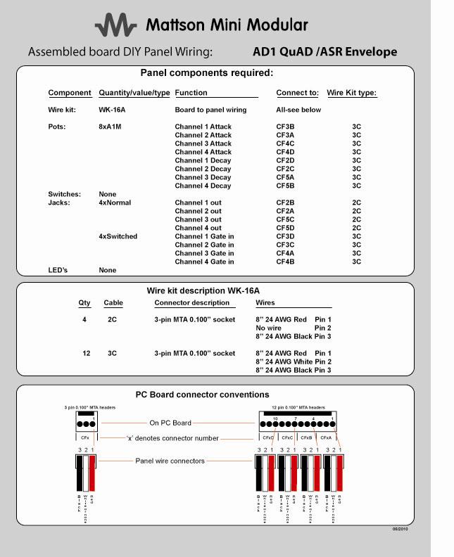
Wiring information:
Availability
This module is available
$84.95
To order, visit the MMM Store
Go to board dimensions and mounting

